ATU-1300™
ATU-1300™ Overview
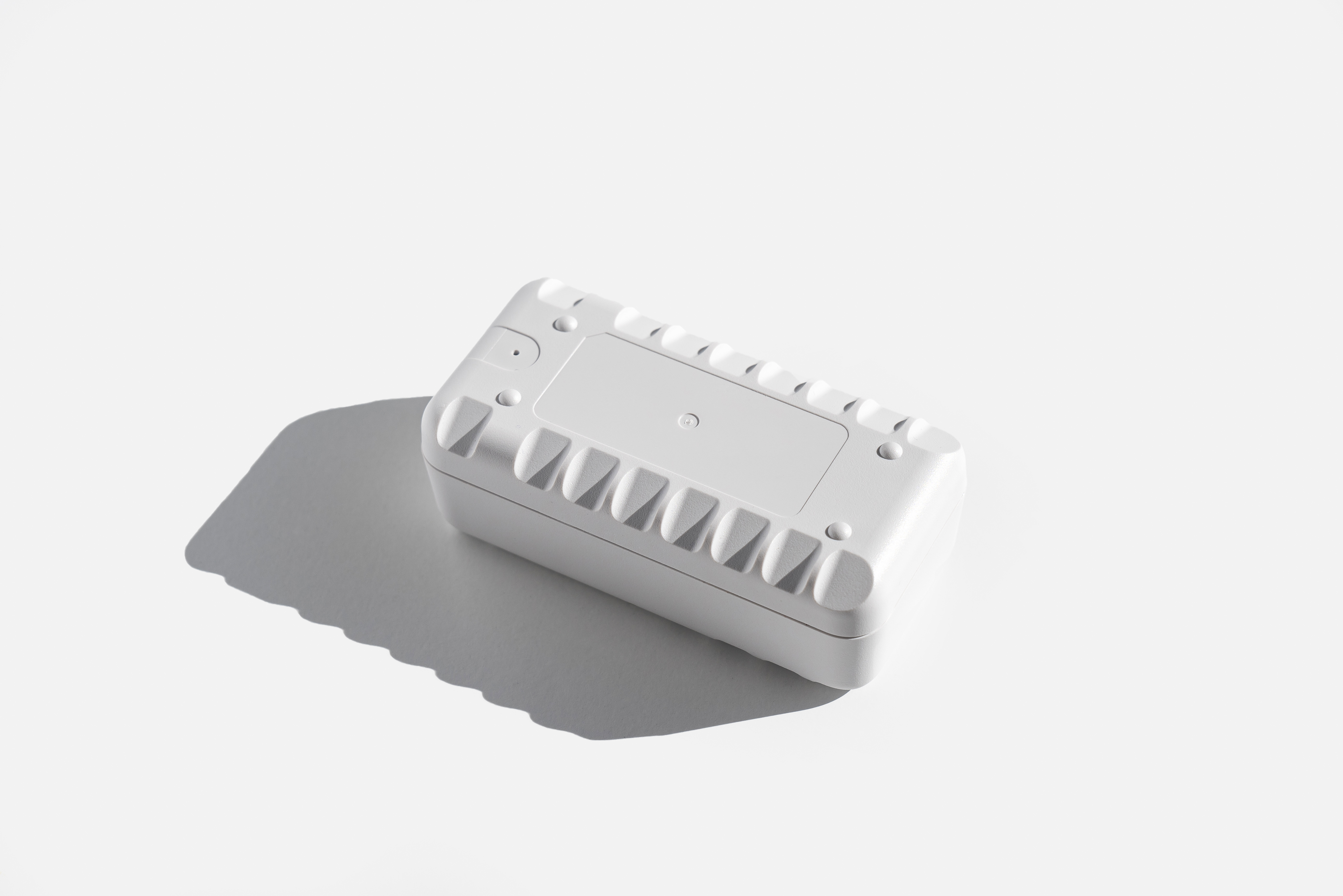
The ATU-1300 is a next-generation asset tracking solution, providing a wide range of use cases and robust applications. The ATU-1300 is sold on a SaaS (Software-as-a-Service) basis, operating in conjunction with a CTC (Calamp Telematics Cloud) Datapump subscription, with an option to upgrade the subscription to the CalAmp iOn Suite.
Please note, that as a SaaS product, the ATU-1300 can only be consumed through CTC Datapump.
CTC APIs and Datapump
Click this link for more information CTC APIs and Datapump functionality
ATU-1300 Reporting Behavior
The ATU-1300 currently offers four reporting profiles, as detailed in the table below:
| Reporting Profile | Behavior |
|---|---|
| [Default] – 1 report per day | Schedule-based: 1 report per day, up to 5 years service |
| 2 reports per day | Schedule-based: 2 reports per day |
| Motion: Start/Stop | Motion Monitoring Enabled |
| Fixed Asset Monitoring | Monitoring fixed position assets (theft detection/tracking), daily scheduled report, and breadcrumb reports if asset moves. |
Scope
This page provides an overview of CalAmp’s Telematics EdgeCore platform, referred as EdgeCore hereafter, the associated products, its highlights and major features. It also serves as a training manual on ‘how-to’ get started with an EdgeCore device (e.g. ATU-1300). Lastly, this document serves to describe the major differences between EdgeCore and the LMU8 predecessor platforms.
Platform Introduction
CalAmp’s next-generation EdgeCore platform features a new embedded architecture and revamped hardware featuring significant advanced capability, reliability, and security. EdgeCore is agnostic to operating system (OS) and Hardware underneath. This section highlights the major features and benefits of the new platform.
Highlights and Features
- A new embedded architecture & framework designed to be adapted on new technologies, hardware chipsets, and operating systems
- Power Management down to sub-milliamp levels during sleep
- 3 axis - Accelerometer (MEMS)
- Delta file upgrade capability
ATU-1300 Hardware Specifications
Cellular/Network
LTE CAT-M1: 2100 (B1)/1900 (B2/B25)/1800 (B3)AWS 1700 (B4/B66)/850 (B5/B26)/900 (B8)/700 (B12/B13/B28/B85)/800 (B18/B19/B20/B27) MHz
GSM/GPRS: 850/900/1800/1900 MHz
Data Support
SMS, UDP Packet Data
Satellite Location (GNSS)
- Constellation Support: GPS/GLONASS/BeiDou/Galileo/QZSS
- Tracking Sensitivity: -157 dBm
- Acquisition Sensitivity: -157 dBm (hot start) -146 dBm (cold start)
- Location Accuracy: <2.5 CEP open sky
Certifications: Industry Certifications: FCC, IC, CE, PTCRB, RoHS, Anatel, Mexico
Cloud/Software Services
- CTC™: Device data stream via RESTful APIs
- Embedded Intelligence Engine
- Geo-Fences: 32 built-in
- Buffered Messages: 20,000
Electrical
Operating Voltage: Hybrid 3.0/9.0 DC internal battery pack
Power Consumption: One report per day - 1825 days
Battery
Battery Capacity: 1500 mAh
Battery Technology: Four CR123A Lithium Primary (LiMnO2) batteries
The ATU-1300 battery is non-replaceable and cannot be recharged. Five year battery life is expected if device reports at once per day under optimal environmental conditions.
Environmental
- Temperature: -20° to +60° C
- Humidity: 65+/- 20% RH @ 50° C non-condensing
- Shock and Vibration: U.S. Military Standards 202G, 810F SAEJ1455
- ESD: IEC 62368
- Ingress Protection: IP67 (CalAmp Assembled)
Physical/Design
Dimensions: 4.01x 1.98 x1.53”
101.8 mm x 50.2 mm (measured at sim door) x 39 mm (measured at knobbed feet)
Weight: 157 g
Connectors/SIM Access
- USB
- Power Switch
- GPS Antenna - Internal
- Cellular Antenna - Internal
- SIM Access Internal - (4FF SIM)
CalAmp SIM Card
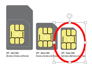
The ATU-1300 will be ordered and shipped as a SaaS SKU (part number) and come with a CalAmp SIM card. The ATU-1300 uses a 4FF (nano) SIM card, which is smaller than the 2FF (mini) SIM card commonly used in prior LMUs.
Preloaded Script
The ATU-1300 is shipped with a preloaded CalAmp script. As configured, it defaults to 1 (one) report a day with motion disabled. Motion can be enabled via SMS or CTC APIs.
The ATU-1300 script is:
- designed for asset tracking @ 1 report a day for 5 years.
- configurable to increase the rate of reporting.
- configurable for motion-based wakeup and/or 5-min breadcrumb.
- configurable with zones and report zone entry/exit.
- configurable for tilt detection reporting.
ATU-1300 Script Design Goal
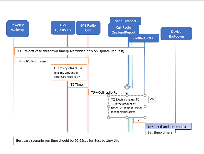
ATU-1300 script is designed to send report based on periodic wakeup, Motion/tilt and breadcrumbs (if needed). The script takes into account the COP+Main processor and single radio design of ATU/LMU-1300 series and optimizes the operations to provide various functions with minimal device runtime.
ATU-1300 Script High level structure
The ATU-1300 script is designed to maximize the battery life of the device for each option provided. It is recommended that the main flow of this script be followed as designed. The main flow of script provides a single run of the device. The device will run these steps in below given order:
-
PEG State 0/Boot: Device is in state0 when power up or wake up. This is the state at which it identifies the boot/wake reason. This state also starts the initialization for runtime and transition to other states based on boot reason.
-
PEG State 1/Init: Device moves to PEG state 1 when Bootreason is identified as “normal mode” and it starts the timers for subsequent steps. Once timers are started, device moves to next state.
-
PEG state 2/GPS Fix: Device by default is configured to wake on GPS Radio ON. This setting is S-reg 183 bit 4 enabled. This bit disables the Modem power at wakeup and restricts the device to using only the GPS Radio. GPS Radio does not need to be stated explicitly. It is automatically started by the firmware upon bootup. PEG State 2 has a timer for 60sec. or GPS Quality fix trigger, whichever happens first. This state also sets the zone. Device also updates the time after a cold boot using the GPS Radio. This state is transitioned with GPS Radio turned OFF (with/without successful fix or max of 60sec timer)
4.PEG State 3/Queue Reports: Device transitions to PEG State 3 after acquiring the GPS Fix. It fills up the reports using the flags and queues the appropriate reports. Typically, only one report should be logged in the queue with each run. There may be historical reports – if unsent previously.
-
PEG State 4/Cellular Connection: Device starts a 50sec timer and turns on the Cellular modem. As soon as COMM is connected, device sends the logged reports. Upon Log empty, it starts a 10sec timer to listen to any server communications and tears down the cellular connection. This state is on for 50sec max. When device transitions to Next state, cellular radio is turned OFF
-
PEG State 5/Preparing for Sleep: At PEG state 5, device clears the flags and prepares to sleep. Based on the current PEG Enables config, Device will sleep on accum schedule or timer.
ATU-1300 Config Settings
The ATU-1300 script handles multiple run scenarios which can be enabled/disabled using PEG Enables. Currently, these are the options supported:
| Feature | PEG Enable Bit (Param 1037) | Default | Event Code | Comments |
|---|---|---|---|---|
| Initial Report | Bit 0 | Yes | 0 | Sends report of init of the device. Sends only once and then accum 0 is updated to 1 to indicate – device was previously used |
| One report a day | Bit 1 | Yes | 1 | Sends one report a day based on accum schedule in accum10 |
| Two reports a day | Bit 2 | No | 1 | Sends two report a day based on accum schedule in accum11 |
| Low battery report | Bit 3 | No | 203 | Sends low battery report when battery level is below 20% |
| Four reports a day | Bit 4 | No | 1 | Sends two report a day based on accum schedule in accum12 |
| Motion Beginning of drive/End of drive report | Bit 5 | No | 4(BOD) and 5(EOD) | Enables motion based wakeup and reports Beginning and End of drive(BOD/EOD) |
| Zone Entry/Exit | Bit 6 | No | 22/23 | Device will report Zone Entry/Exit |
| Watchdog | Bit 7 | Yes | 1 | Sends weekly report based on accum schedule on Accum2.This is a failsafe option. This schedule is reset if device wakes up within a week |
| Tilt Detection Reporting | Bit 8 | No | TBD | |
| LED Control | Bit 9 | Yes | Script controls the LED. 5 secs for GPS and 3 secs for Cell. Disabling this would cause the LEDs to be OFF. | |
| Breadcrumb | Bit 10 | No | 6 | Needs to be used with Motion wake (Bit 5). This option provides 5 mins breadcrumb with BOD/EOD Reports |
| Not used | Bit 11 | No |
Flag Group 0-7 : Operational Flags
- Flag 0 : Device operational
- Flag 1: Cold Boot
- Flag 2: Not used
- Flag 3: Wake on Timer
- Flag 4: GPS Radio ON
- Flag 5: GPS Radio OFF
- Flag 6: Event Reports Exist/ Turn ON Radio
- Flag 7 : Cell Modem Turned OFF/Prepare for sleep
Flag Group 8-11:
- Flag 8 : Zone Entry
- Flag 9 : Zone Exit
- Flag Group 12-15: Live Reports
- Flag 12: 24 hrs report expired
- Flag 13: 12 hrs Report Expired
- Flag 14: 6Hrs Report Expired
- Flag 15: 7 Day watchdog Report Expired. This flag is also set if failsafe timer is the wakeup source
Flag Group 16-19 : BOD/EOD/Breadcrumb
- Flag 16 : Wake on IO with Input 1 high/BOD
- Flag 17: Wake on Timer with Input 1 low (provided Flag 16 is set)/EOD
- Flag 18: Wake on Timer with Input 1 high(Provided Flag 16 is set)/Breadcrumb
- Flag 19: Not used
Flag Group 20-23: Misc
Flag 20: Battery low indication
Flag 21: Battery Low indication report sent
Setting PEG Enables with API DeviceCommands
PEG Enables are stored as bitmask in parameter 1037. The bitmask value is a 4 byte number.
When using the DeviceCommands API to update parameter 1037, an 8 byte value has to be sent as hexadecimal. The value to send in the POST API call has a format of: 0x[MASK][Value]
MASK are the bits you want to change – 4 bytes
Value is the bitmask value you want to set – 4 bytes
As an example, to set bit 8, use a value of 0xFFFFFFFF00000100 OR 0x0000010000000100 depending if you wanted to manipulate the other bits in the bitmask.
POST /devicecommands/device/{id}/parameterconfig/{parameterid}/{index}/{value}
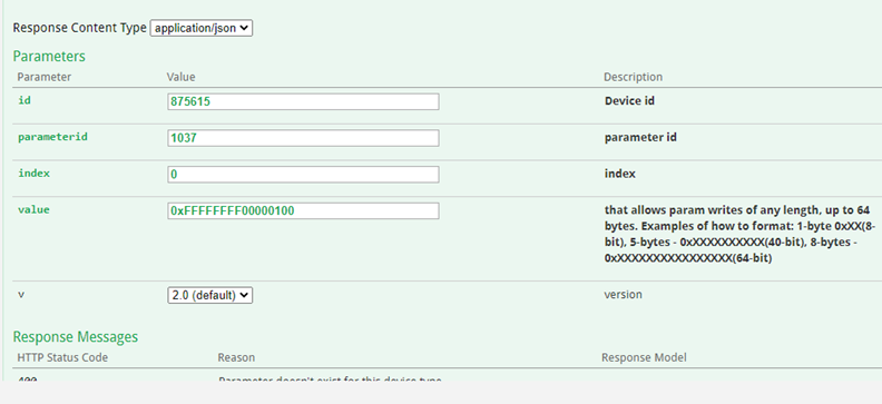
That API call will set the value of param 1037 to 256 (only bit 8 set)
This is similar to how you set the bitmask through AT commands, except values are in decimal.
at$app param 1037,Index,Mask,Value < -- AT command format to set param 1037
at$app param 1037,0,4294967295,256 < --- sets param 1037 index 0 to 256 - PEG enable 8 only is True
at$app param? 1037,0 < --- queries the value of param 1037 index 0
ATU-1300 Flags, Timers, Accums
The ATU-1300 Script makes use of timers and flags to run thru the logic. Most flags are cleared on sleep – except when BOD/EOD/Breadcrumb is used.
PEG Flags are stored in Accum 4 and sent with Alive reports. This can be used to understand the state of the device for debugging purpose.
Timers
| Timer | Value | Usage |
|---|---|---|
| 0 | Not Used | |
| 1 | 130 | Max Run timer, Starts at PEG state 1 and on Expiry – makes device sleep. Note: This time should always be 10sec more than Worstcase GPS runtime[Timer 4+Timer 5]+Worst case Cellular run time[Timer 6+Timer 2]. |
| 2 | 5 | Inbound Server Comm Wait Timer This is the amount of time device waits for communication with server once the message queue is emptied. if you see that messages are not being sent fully or not being received by the device, increase this timer to 10sec. |
| 3 | 600 | OTA Update Timer, Device starts this timer to delay sleep when OTA update notification is received. It can be script, COP or LMU. Once Update End is received, this timer is cleared, and device goes to sleep. |
| 4 | 60 | GPS Run Timer, timer is started at PEG state 1 and is the maximum GPS Radio run time. This timer is cleared when GPS Fix is acquired. |
| 5 | 2 | GPS timeSync timer, this timer is started when GPS Fix is received. Using this timer helps all LMU subsystems update time received from GPS. if you see that GPS fix is received but GPS timeSync does not happen or is missing Zones etc - increase this time to 5 sec. |
| 6 | 50 | Cell Radio Run Timer, this timer is started when Device starts Cell Radio and expiry of this timer, tears down the cell connection. Timer is cleared when Message queue is emptied + Inbound Server Comm Wait timer. |
| 7 | 86400 | Failsafe sleep timer, this timer is the sleep timer on which the device sleeps if timesync does not happen and accum schedules are not init. If device fails to wake on accum schedules or motion – device will wake on this timer as this is not dependent on timesync. |
| 8 | 3 | LED Run Timer, this is the amount of time LEDs glow when Cell/GPS radios are connected. |
Accumulators
| Accum0# | Accum Definition | 279 | 280 | Threshold/Value | Comments/Troubleshooting the script&device |
|---|---|---|---|---|---|
| Accum0 | Main Battery Remaining in Percentage | 25 | 0 | This is the only accum shown in the SAAS peg behavior. For below other accums, pls read raw data | |
| Accum1 | COP Battery Remaining in Percentage | 25 | 1 | All of our test show that COP battery has higher life than Main battery but erroneous motion wake may cause this battery to deplete. If device no longer wakes up, then pls check the data in this accum | |
| Accum2 | Watchdog Accum Schedule | 26 | Epoch timestamp For Wake on Weekly Report/PEG Enables 7 | ||
| Accum3 | Init Indication | 0 | Set to 1 if unit has been powered up. Otherwise, number of wake cycles of the device. This accum is incremented at every wake | ||
| Accum4 | PEG Flag accumulator | 0 | This is accumulated right before Event reports are populated. Flag status for reports to be sent. Pls look at the flags section to correspond this data. This data is collected right after GPS acquisition in a wake cycle | ||
| Accum7 | Counter for ID report | 0 | Threshold is set to 7, increase or decrease for ID report frequency change. | ||
| Accum8 | GPS Quality | 50 | Reports GPS fix status, # of Sats and HDOP | ||
| Accum9 | Cell RSSI | 13 | |||
| Accum 10 | 24hrs accum Schedule | 26 | Epoch timestamp of next wakecycle - if set to 24hrs report. PEG Enable 1 | ||
| Accum 11 | 12Hrs Accum Schedule | 26 | Epoch timestamp of next wakecycle - if set to 12hrs report. PEG Enable 2 | ||
| Accum 12 | 6hrs Accum Schedule | 26 | Epoch timestamp of next wakecycle - if set to 6hrs report. PEG Enable 4 | ||
| Accum 13 | Operational | 0 | |||
| Accum14 | Not used | ||||
| Accum19 | ADC for Temperature | 5 | 12 | KPI Data: Collect the ambient temp of the device. | |
| Accum22 | GPSRadio Runtime for Current WakeCycle | 0 | KPI Data | ||
| Accum23-30 | KPI Data: Battery usage data for debugging | 25 | 0-7 | Battery Data collected in Remaining Percentage, mAh etc. for both main processor and cop |
Motion wakeup is based on COP waking the BG95. This is based on TTU Style motion. Default param values
Params:
- Motion Range/912 : 128 to enable TTU Style motion
- Param 1038: Motion Threshold-Low/lo_cnt: 3 cnt
- Param 1039: Motion Threshold-high/hi_cnt: 6 cnt
- Param 1040: Motion Max Count/max_cnt: 7 high
- Param 1041: Motion Detect Window: 1 sec
- Param 905: Motion threshold: 5
- Param 907: Motion Poll period : 10
When LMU/BG95 is awake COP is awake.
When COP is awake, it does not check for motion. Motion Transitions are not captured when BG95 is awake. COP is in IDLE state when BG95 is awake. COP only Polls for motion interrupt when BG95 is asleep.
If count for Motion High wake has started and BG95 wakes for “Alive” Report, then BG95 will resume the Motion High counter after BG95 is asleep
When BG95 is asleep, COP itself sleeps and wakes on scheduled timer wake
if motion is enabled, then COP can detect motion high quickly within the 10secs window but once it detects motion and is in IN-MOTION state, the COP takes max_cnt0.75-(lo_cnt-1))255 secs to detect – motion low.
ATU-1300 Motion Wakeup and Breadcrumbs
3-Axis Accelerometer
The ATU-1300 supports an internal 3 Axis Precision Accelerometer as one of its discreet inputs. When the LMU is moved in any direction, the associated input will be in the High state. If the LMU’s accelerometer does not detect motion, then the input will be in the Low state. No external connections are required for this functionality to be operational.
Status LEDs
The ATU-1300 has 2 status LEDs, green and amber, to indicate GPS/Cell status. Verify LEDs are operational upon switching device to ON.
Note:
Upon installation, the ATU-1300 LEDs will only be on during check-in with the platform.
Status LED Behavior
Standard LED behavior detail can be reviewed in the table below:
LED Definitions and Behavior
LED #1 (Comm LED – Orange or Amber) Definitions
| Condition | LED 1 |
|---|---|
| Modem Off | Off |
| Comm On - Searching | Slow Blinking |
| Network Available | Fast Blinking |
| Registered but no Inbound Acknowledgement | Alternates from Solid to Fast Blink every 1s |
| Registered and Received Inbound Acknowledgement | Solid |
LED #2 (GPS LED – Green or Yellow) Definitions
| Condition | LED 2 |
|---|---|
| GPS Off | Off |
| GPS On | Slow Blinking |
| GPS Time Sync | Fast Blinking |
| GPS Fix | Solid |
Getting Started
Warning
Proceeding with the removal of the ATU-1300 access port cover eliminates the IP67 rating. Water ingress as a result of improper customer sealing voids CalAmp warranty.
With any new platform, there are some changes in the form, fit, and function when compared to the predecessor product line. This section highlights pertinent changes introduced to the ATU-1300, such as accessing the SIM port, and installing the device.
Removing Access Port Cover
To remove the cover and access the SIM Slot and On/Off switch, use a fingernail or a soft plastic spudger to wedge into the groove, shown below:
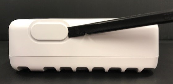
Accessing SIM Slot and On/Off Switch
After the access port has been removed, the SIM Port and On/Off Switch will be accessible.
- 4FF nano SIM slot
- On/Off Switch
- Micro-USB port
- Debug port
SIM Insertion
If the ATU has been purchased from CalAmp with a SIM and data plan included and the SIM is already installed, skip to the next step.
If the device has been purchased from CalAmp without a SIM and data plan, insert a 4FF SIM into the SIM Slot prior to turning on the ATU. The 4FF (nano) SIM from a carrier or MVNO should be provisioned for use on a compatible Cat-M1 network.
The SIM slot is a spring actuated push-push slot. Insert the SIM with the keyed end first and the contacts facing the USB port.
ON /OFF Switch
If the device has been purchased from CalAmp with a 4FF SIM already installed, toggle the On/Off switch from left [Off] to right [On].
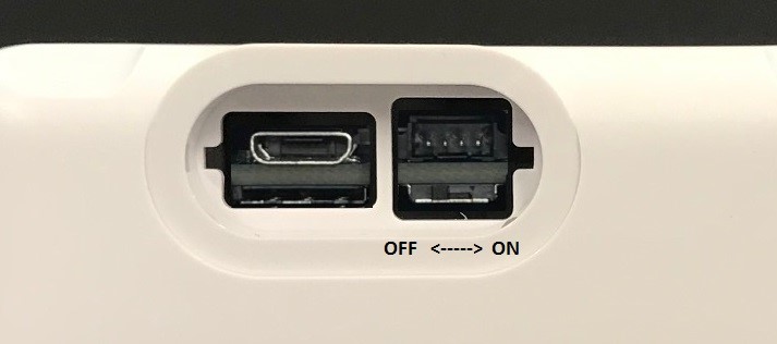
OFF is the switch position closest to the SIM slot. ON is the position away from the SIM slot.
Replace the Access Port Cover
Carefully replace the access port cover, ensuring the inner snap tabs are aligned with the notches and the gasket is not pinched or protruding, when pressing in place. Inspect to ensure the cover is flush with the housing on all sides.
Installation
Mounting Options
The ATU-1300 has three mounting options – please verify individual use-cases to determine which works best for your business application.
• Zip Ties – to be affixed onto retention ribs
• Double-Sided Tape – places onto bottom side of the device (with label and retention ribs facing upward)
• Mounting Bracket (Part number 13600005) – Optional, Sold Separately
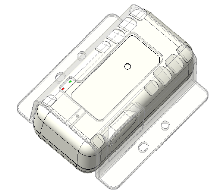
Diagram: ATU-1300 with optional mounting bracket
Installation Verification
Once the ATU-1300 is mounted, the following steps are to be taken to verify the device is operating functionally.
- Observe the LED function to ensure compliance with the behavior detailed on this page
- Verify the device checks in to the DM-CTC platform
- Verify event visibility in CTC Admin or the CTC iOn Suite

Updated almost 4 years ago
