EdgeCore Detailed Design Documentation
What is CTEC?
CTEC is CalAmp’s Telematics Edge Core diagnostic platform that includes the “Location Message Unit” (LMU) edge firmware and "Vehicle Bus Unit" (VBU) data collection firmware. CTEC can be considered a 'telematics stack' that provide a list available and customization services usable in multiple IOT verticals. CTEC resides on edge devices of various forms, to provide telemetry and telematics data to the “CalAmp Telematics Cloud” (CTC) and contains a "Programmable Event Generator" (PEG) that can be statically or dynamically configured via CTC. CTEC is highly modular, and highly adaptable to an array of applications and hardware platforms.
CTEC is designed to be a standalone platform, but can also be integrated onto a SoC with an existing set of applications to achieve a high level of silicon integration reducing BOM costs. CTEC itself can also function as a distributed platform across multiple micro-processors with differing BSP's.
CTEC Design Advantages
The design advantage of CTEC is its Architecture. Functionality within CTEC is modular and contained in independent threads. Great care was taken to allow individual modules be quasi independent of each other, yet still have the ability to communicate and interact with each other. This is accomplished by having a Common Architecture Framework, which are a class of constructs that all threads/tasks/queues utilities to perform their function and inter-communicate. Test-ability and self documentation is built into the architecture at the function, API, module and systems levels.
The fundamental goals of this architecture is to support the following items:
-
Modularity – one module envelops one concept.
-
Commonality – across modules. Improves maintainability and new architectures.
-
Reliability – an architecture that built in provides thread safe operation to avoid race conditions, mutual exclusion, and other common multi-threaded pit falls.
-
Testability – testability built in with full public API test-ability via CLI's and Google Test Framework, allows testing during compilation and Continuous Integration.
-
Adaptability – to architecture changes required for future derivations of the product.
-
Portability – from Linux to RTOS environments like ThreadX and FreeRTOS.
-
Scalability – can support large, medium and small memory models.
-
Sleep functionality – includes a platform level power state machine, and optimized for extremely low sleep current applications.
-
Documentation – high level designs, coding standards.
CTEC Telematics Platform, or EdgeCore
CTEC represents a repository of modules that are quasi independent in nature. They are independent in the fact that they all represent some individual function, but dependent that a group of them together is required to provide the complete telematics stack functions. This is accomplished by associating a platform with the CTEC repo. The platform and the inclusion of the various CTEC modules would make up a complete functional telematics device and provide the functionality of the requirements of the product. Thus, CTEC is really a library of components that combined in some combination provide the desired telematics solution.
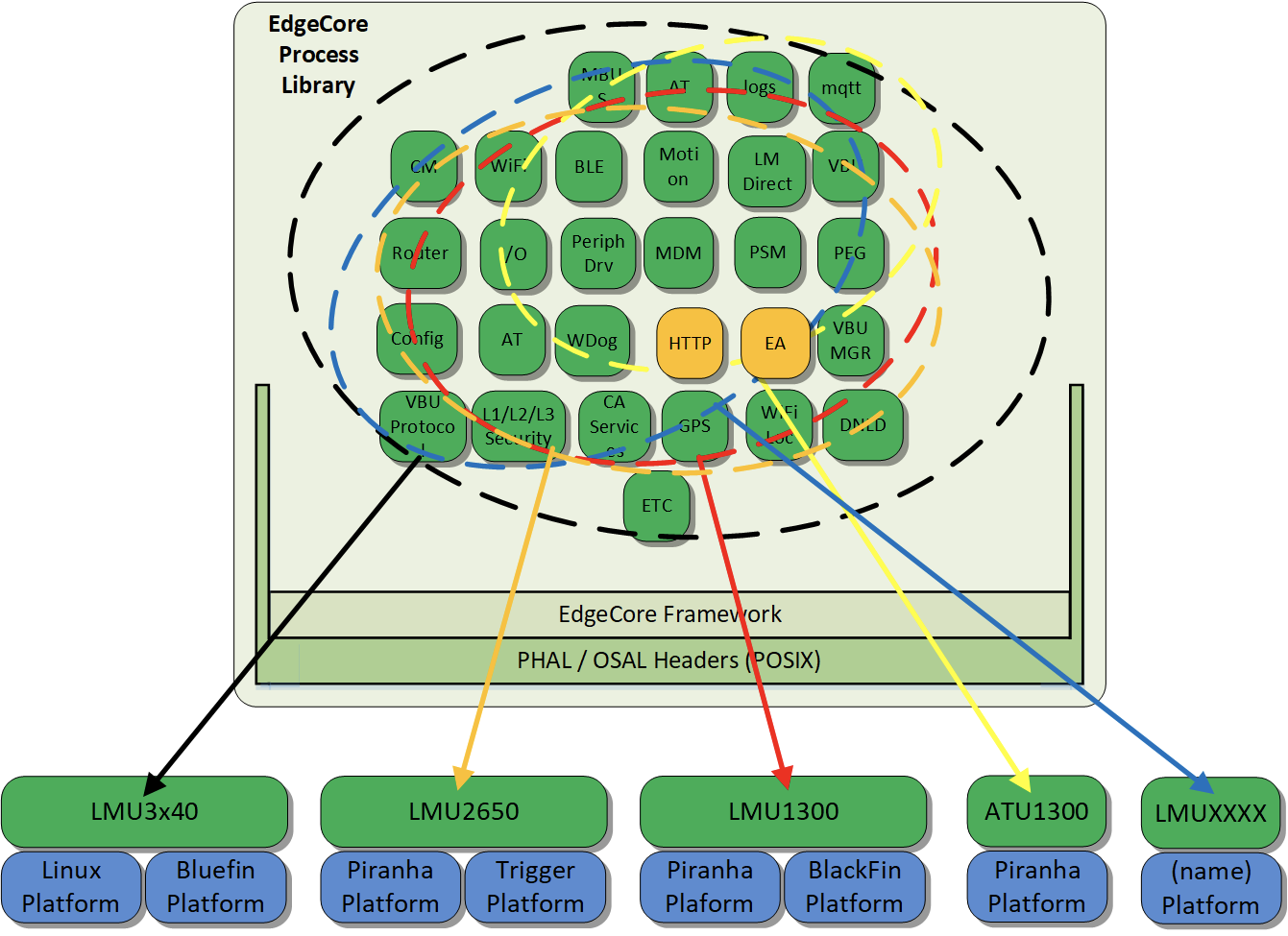
CTEC LMU Telematics Services
LMDirect, PEG, and DNLD represent the the essence of the LMU. These contain the parameters, and logic that represents the operations of the LMU. Accumulators, PEG script operation, and LMU Network services. Generic information about the device condition are provided by the LMU Enabler Modules. This information includes location, motion, power control, network status and wan/lan services. This information can be acquired by public API to the LMU Enabler Modules, or event driven via the system message bus.
| CalAmp LMU Modules | Services |
|---|---|
| LMDirect | Public inbound serves (UDP/TCP) event reporting Private inbound services (UDP/TCP) event reporting ID Reports Application Messages FOTA services Loss of service persistent logging |
| PEG | Programmable Event Generator |
| ATCmd | Configuration queries test |
| CalAmp Services | ICN Device TAG support L2 security, TLS |
| DNLD | FOTA Device Capabilities Device FW/Data inventory |
| EdgeApp | Customization of CTEC services |
CTEC Generic Telematics Services
LMU Enabler Modules are those subsystems that are used in the LMU to acquire data, but have no specific knowledge of what an LMU is. They are responsible for managing the associated module, and the data that is associated with it. There are public APIs that are available to access data, and configure the module. Additional change of state, or event driven data will be provided by publicly published message bus channels. There are no specific PEG/Event/Trigger/LMDirect functions to associated with this module at all.
| LMU Enable Modules (Generic Modules) | Services | Description |
|---|---|---|
| VBUS | J1979 J1939 J1850 J1708 Kline Taco-graph Canilizer | Supporting Modules: VBUDriver VBUManager Protocol Controller Protocol State Runner |
| Motion | MEMS Sampling Alignment Acceleration Measurements Driver Behavior Motion logs | |
| GPS | Location reporting/status Speed/heading Towing n-Hz Position reports Last known GPS Time | |
| Connection Manager | LAN connectivity and connection services WAN connectivity and connections services Least Cost routing. DNS Services Dual APN | Supporting modules: Modem WiFi USB Router |
| Power Management | ||
| GeoZones | Zones GeoZones | |
| SMS | Configuration Query Control | Supporting Modules: Modem |
| I/O | Supporting Modules: I/O Peripheral Driver | |
| BLE/BT | SPS (NMEA stream, AT Command Interface, logging) BLE Tags Fobs | |
| Watchdog | System Reliability | |
| Config | Parameter storage Persistent run-time data File System services |
Typical CTEC Telematics Stack
The following diagram represents the typical hierarchy of a telematics stack. At the bottom of the stack is the generic process that enable hardware or algorithms in gathering telemetry and telematics information. These modules should contain only algorithms and API's that related the function being managed. Example, the GPS module should only interface with a GPS engine, and related functions, like GPS related speed, or direction prediction. These modules should be designed such that they can be added or removed without significantly effecting other modules either adjacent or above other that the featured is not longer available. These modules should report up data based on event, and can via API. Ideally access to these modules should be event based. Control and configuration must be done via API.
The purpose of the Message Bus (MBus) is specifically accommodate the above statement. The MBus is designed to share public information to other adjacent or higher level applications. Using the MBus detaches modules from directly access each other, and can indirectly indicate if adjacent processes exist based on the existence of the associated MBus channels.
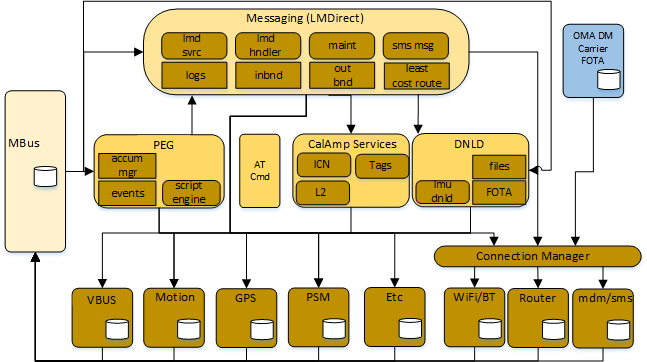
The top level sub-systems like LM Direct, PEG and Dnld are CalAmp Telematics services that bring the functionality of lower level components into a working telematics system. The linkage between the CalAmp services and the generic services are public API's and message bus events. The existence of the message bus allows the CalAmp telematics stack to be fully event driven. This architecture suggests that CalAmp services can be replaced by or added enhanced by additional off the shelf telematics services. Example, LM Direct is the main reporting protocol for back end our cloud services. This can be replaced or enhanced by adding the MQTT services.
High Level FW Architectures
The following sections outlines the currently existing platforms that utilize the CTEC telematics stack. Most of the implementation below are multi processor implementations, but in all cases, the main LMU or main telematics stack is integrated onto the modem module applications processor reducing the total amount of required silicon. The co-processors are required to supply:
- extreme low power modes for battery preservation or low current draw on the supplying system.
- additional I/O functions like ADC, GPIO, and other discrete and analog peripherals.
- additional serial peripherals to support vehicle bus connectivity, UART, CAN.
- to support other LAN/WAN based wireless protocols like BT or WiFi.
Simpler LMU that have less of a requirement on peripherals can and will be residing entirely on the modem, and may employ an IO Expander to allow for more complex functions without the maintenance and cost of a second micro processor.
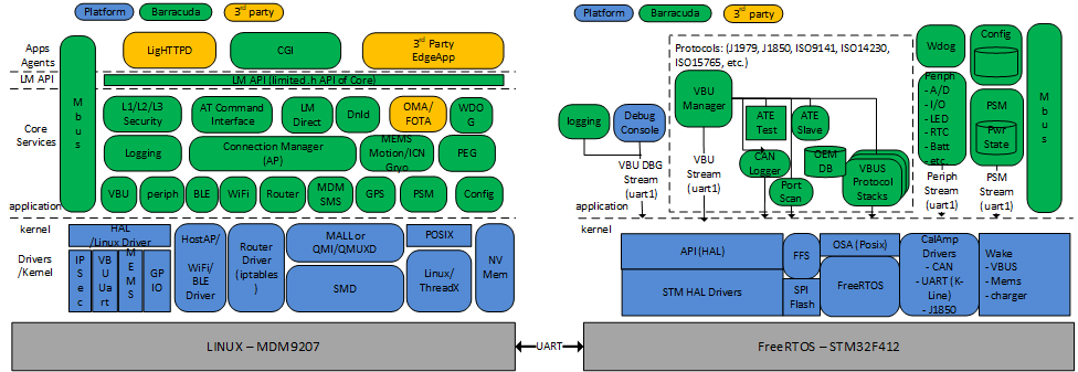
LMU3040, LMU3240, and LMU3650
This group of LMU's are based on the WNC MDM9207 module as the main processor and uses an STM M4 Cortex as the co-processor. These processors supply the following functionality.
The main LMU processor is Linux based and supports:
- LM Direct protocol
- PEG2 Programmable Event Generator
- Dnld over the air firmware, script and file download services
- L1 through L3 security (partly supported now)
- Connection manager support for LAN/WAN connectivity
- LTE, and HSPA modem support
- Motion, driver behavior, and Crash-box
- GPS
- WiFi AP (router) and Client, dual channel
- BLE, with central, peripheral, broadcaster and observer supplying SPS, Tags, Advertiser and Fobs
- SMS
- AT Command interface for control and configuration
The Co-Processor is FreeRTOS based and supports:
- Power management, low power mode.
- GPIO and ADC,
- Charging management
- Vehicle bus support (J1979, J1939, J1850, J1708, Kline)
An Additional CC2640 or QCA9377 module:
- WiFi or BLE physical layer/dataline layer communications support
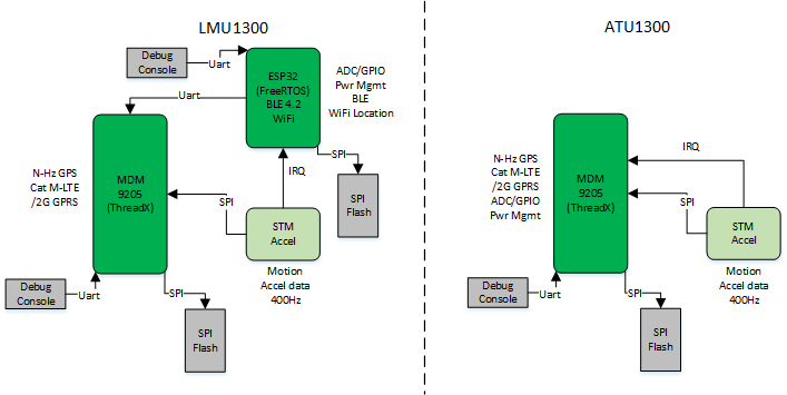
LMU1300
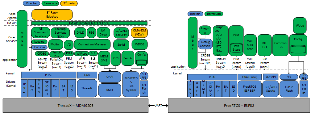
The LMU1300 are based on the QuecTel MDM9205 module as the main processor and uses an ESP32 as the co-processor. These processors supply the following functionality.
The main LMU processor is Threadx based and supports:
- LM Direct protocol
- PEG2 Programmable Event Generator
- Dnld over the air firmware, script and file download services
- Connection manager support for LAN/WAN connectivity
- LTE, and GPRS modem support
- Motion, driver behavior, and Crash-box
- GPS
- WiFi Location
- BLE, with central, peripheral, broadcaster and observer supplying SPS, Tags and Advertiser
- SMS
- AT Command interface for control and configuration
The Co-Processor is FreeRTOS based and supports:
- Power management, low power mode
- GPIO and ADC
- Charging management
- WiFi or BLE physical layer/dataline layer communications support
ATU1300
The ATU1300 are based on the QuecTel MDM9205 module as the main processor. This processor supplies the following functionality.
The main LMU processor is Threadx based and supports:
- LM Direct protocol
- PEG2 Programmable Event Generator
- Dnld over the air firmware, script and file download services
- Connection manager support for LAN/WAN connectivity
- LTE, and GPRS modem support.
- Motion, driver behavior, and Crash-box
- GPS
- SMS
- AT Command interface for control and configuration
- Power management, low power mode
- GPIO and ADC
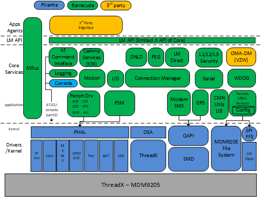
EdgeCore or CTEC Framework Architecture
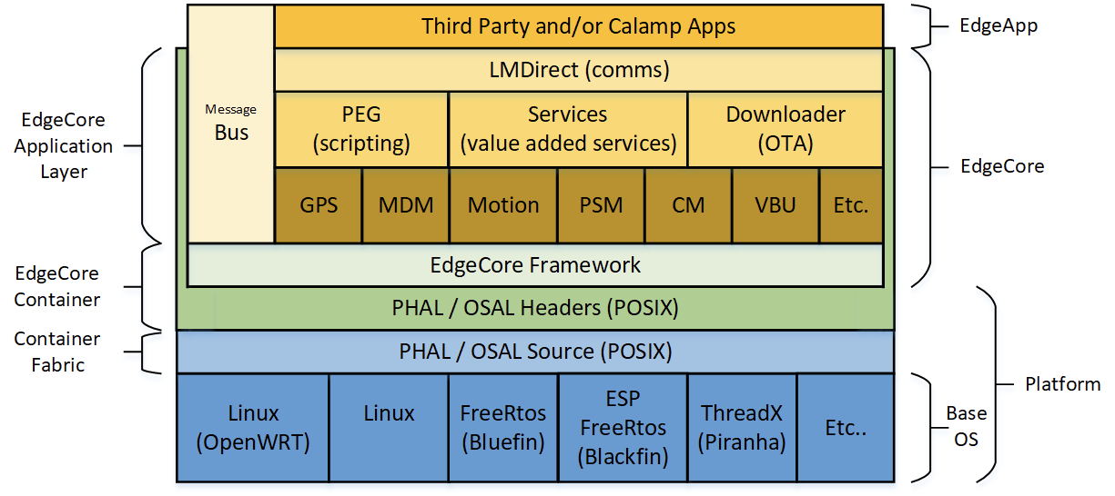
The above diagrams show specific platforms that utilize the EdgeCore modules to create a specific LMU type. These LMU's pull from the CTEC repo to grab modules and supply various LMU functions. This section describes the general architecture of EdgeCore.
An LMU utilizing CTEC has four distinct layers:
Platform: This layer contains the operating system, device drivers and hardware that is the basis of the LMU and derives the features and applications that can be supported. This layer is NOT part of CTEC, but a platform that can host CTEC. The minimum requirements for this layer is a Kernel that supports threading, semaphores, queues, and shared memory objects, 1MB of flash and 1MB of RAM. This is referred to as the Platform or BSP.
PHAL and OSA: The Platform Hardware Abstraction Layer, and the Operating System Abstraction. These two layers are also not part of CTEC, but the header files of the PHAL and the OSA represent the interface layer between CTEC and the platform and are which allow CTEC to be hosted on multiple platforms. The Platform, combined with the OSA/PHAL can host CTEC Applications.
CTEC Framework: CTEC represents a group of process/threads that provide the LMU FW features. These process/threads all have a common class or object structure that they run from. They are all derived from the Sub-System generic process (described below). All these common structures like tasking, IPC, mutex's, semaphores are derived and exist in the Framework layer.
CTEC Applications: These are the specific applications that combine together to create a CalAmp LMU.
Module File structure and build.
The file structure for CalAmp added modules will follow the format below:
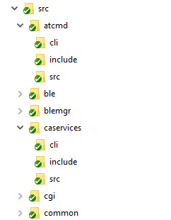
Every CTEC Process has a similar internal structure and looks the same in the file system. The above file explorer view show a few of the CTEC process, or subsystems and expands the directories supported by each subsystem, which are:
- cli – this contains the source for the self test module.
- inc – this contains the public api interface .h file.
- src – this contains all the source and header files for the module.
In the Linux environment, each module will be built as an individual process and place in a similar directory in the artifact root, where as in the RTOS environment, a single image is build of all the CLI's and applications. Linux processes and threads simply become tasks.
CTEC or EdgeCore Module high Level designs
The following sections describe some of the more significant components or subsystems of the CTEC platform. All CTEC subsystems have a detailed design section here so the sections following will only give a brief description of their functions, and may also combine multiple related subsystems to give a system description.
Subsystem Template Process
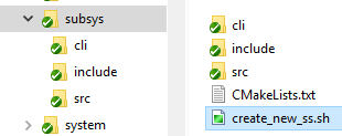
This self named subsystem is the generic template and starting point for all CTEC process. It contains a basic CLI, a basic public interface, and the basic shell application that allows it to startup, shutdown, and participate in basic power state changes, has a basic Message Bus handler, and registers with the watchdog. It also contains a basic example thread, and an example of multi-instance thread. This basic application hosts no specific features for an LMU but is used for a few very important reasons
-
It the basis for any new CTEC subsystems to be created. By calling the script "create_new_ss.sh" in the Linux environment, a new copy of a subsystem can be created by entering the name. So if for example you wanted to great a GPS module. Call this shell script with gps as a command line input, and a new subsystem is created and renamed with the files, and all the internal symbols.
-
It is used to test the a new platform/OSA/PHAL when bringing up the framework on a new platform.
-
and it is used to enhance and debug existing framework functions.
Process Model
The process model of a subsystem is one example process, and internal generic example thread, one example multi-instance thread, a timer example, and background task example. Also the use of IPC using the mque module using single or dual queues for by-directional communications.
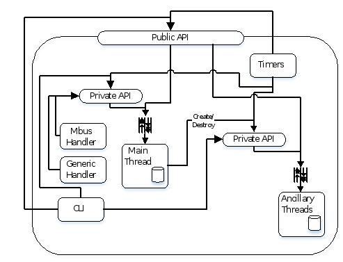
This same model can co-exist in the Linux environment as a process, thread module where the process is started by the RC Init script, and then the process starts ancillary threads as required. Similarly, in the RTOS environment, the main Linux process is the starting task that can start ancillary tasks as required.
Process/Thread Flow
Active modules will follow the architecture, whereas passive modules would simply be the Module API and CLI.
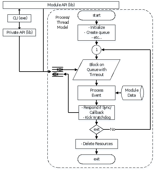
The Module API and Private API shall exist as libraries. In active process, these libraries will make asynchronous and synchronous calls to the process thread via POSIX message queues. This architecture protects the internal data class from being manipulated via multiple threads of differing priorities and causing race conditions or mutual exclusion issue. All event, timer, and general API access and processing will occur in the context of the thread via the API's which blocks on the Message queue. This architecture is similar to using a semaphore on each function call as a queue is simply a list and a semaphore, but in this case, the semaphore is hidden. Library only modules that manage a resource will required the use of a semaphore.
In this model, asynchronous and callback type function calls are not blocked using a message queue as it would be just simply using a semaphore. Only functions requiring synchronous access are blocked until the thread get around to its request. This architecture reduces the possibilities of priority inversion and thread starvation.
Watchdog
The watchdog sub-system is a CTEC application that monitors all active process and threads in the CTEC repo and provides guarantied operation of all functions. This is a software watchdog, which in-turn monitors the BSP hardware watchdog. The purpose of the CTEC Watchdog is to detect an individual task of execution that if it fails, deadlocks, or crashes, will cause as system watchdog to occur. If all threads pet the same hardware watchdog, then any one or more threads can fail and the system will still remain partly running, likely going unnoticed. This software watchdog does not allow this to happen.
After an individual thread fails, the watchdog subsystem will report the offending task that failed, and reset the system.
All process and threads are required to register to the watchdog, then periodically pet the watchdog. If at process exist, it can de-register from the watchdog subsystem.
Message Bus
There are two types of communications available in the CTEC platform. One is the public interface, the second is the system message bus. Both of these methods use mque's module using IPC to perform their functions.
The message bus subsystem is exactly what the name says. It is a common one to many async-messaging system. Any task can create a channel, any task can write to a channel, and any process can register to the message bus to get event driven message response. The typical or desired use of the message bus is that an application will own a channel, as such it will create and write to this channel. Any number of non-channel owner application can read the channel, or subscribe to the channel to get messages updated as they are written. This allows for applications to detach themselves from other applications by avoiding direct functions calls.
The message bus is based on the generic subsystem platform and thus is a portable application with CTEC. This application, like the watchdog, is integrated to each subsystem process.
Config
The config module is the subsystem responsible for the storage of all persistent CTEC data. As the name suggests, it is for configuration data, but is not limited to just this. This subsystem provides all persistent data storage including:
- Configuration Parameters - traditional PEG parameters that are script downloadable.
- Files - a flat file system for all files, including OTA downloaded files and the PEG2 script.
- Persistent Runtime Data - run time data that is to be stored during sleep, or over a reboot cycle. Cases where system memory is not preserved, the the run time data must persist.
Config utilizes the underlaying platform file system. The intention of config is not to replace or be a file system, but rather an abstraction of the platform filesystem that also confirms and works with the CTEC architecture.
Power State Manager
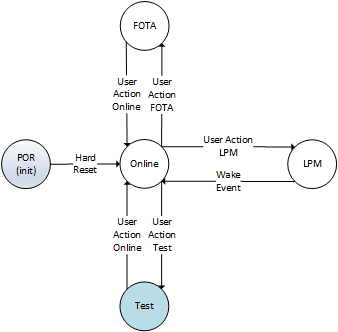
Power State manager is responsible for system level power transitions. This may include a series of Low power levels and sleep states to facilitate minimum power utilization. Power manager may be required to manage what core process are allowed to run when in the various power levels, in particular those with hardware components associated with them.
Levels should be of the following:
-
Online – all modules functioning normally, all hardware periphery enabled.
-
Low Power Mode – external hardware disabled, Core systems are shutdown to the minimum level to support the specified wake-up sources.
-
FOTA – Specific to Firmware Update and some services may be disabled to stop processing that may affect or interact with systems that are having the FW update.
-
Test - manufacturing and general test. In this state, the PSM or Local Process do not typically drive the state engine. Transitions to and from this state are performed by user intervention.
The power state machine (PSM) is designed in a master/slave configuration. In some hardware architectures, it is required to have a separate power processor that will allow the LMU as a whole to achieve minimum power considerations. In this case, as illustrated in the top diagram in the below figure, that the co-processor contains the Master PSM where control of power states are maintained. Also, in this case, the main processor is usually powered off, (unless radio active wake is required) to conserve power. The Slave PSM that exists on the LMU is strictly to supply local process API access to power management commands.
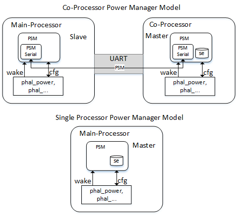
A second configuration is Master only. This case there is only one processor, the main LMU and it is also the Master PSM. In this case, the PSM Serial drops off and there is only one instance of the PSM. This is #define configurable.
The PSM calls into the phal_power.h/c modules what supply the platform specific requirements to control the power levels of the device. The phal_power.h is generic .h across all platforms.
Connection Manager
Connection manager and the associated subsystems main function is to provide either local or broad band connectivity to the device based on device configuration. The associated subsystems are the following that may or may not participated in overall connection establishment
- Cellular Modem
- Router
- Wifi
- BLE
- USB
- NIC
Connection manager is the glue logic that will dynamically configure interfaces to play WAN or LAN roles in data connectivity, as well as maintain connections, establish new connections, and take connections down.
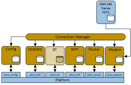
Connection Manager itself does not directly manage the interfaces, rather interacts with the subsystems that do via public API, and message events associated with the various subsystems. Connection managers logic is based on how the device is configured. Such configurations can be a Router AP, or Least cost routing configurations. Connection manager would maintain connection back-off and re-establishment logic.
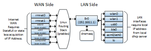
WiFi Hotspot
One of Connection Managers task is the configuration of the Router and Access Points. The following diagram portrays a visual description of the a Linux based router configuration. In this case, a LAN base bridge configuration allows a simplified means to allow LAN client access router services, where as the Linux routing stack performs the WAN to LAN connection points providing NAT based Private IPV4 and IPV6 connections to provide local and connected clients with internet connectivity.
Least Cost Routing
Least Cost Routing is a priority based scheme that is also a responsibility of Connection Manager. In this case, local telematics traffic is routed over the lowest cost configured and available interface. Configuration data determines the priority scheme and participating interfaces.

PEG
This is the CalAmp PEG engine responsible for executing the scripts providing actions based on triggers from the various services like MEMS, VBUS, I/O, GPIO, LAN Connectivity, GPS, SMS and Power.
AT Command Interface
Support the AT command of the Debug Console. Required by development, ATE, Test.
Mems and Motion
This modules interact with the MEMS devices providing input information to PEG, Crash Box and LM Direct.
I/O
Monitors the state of the IO.
OMA and FOTA
These modules provide for Over the Air Firmware Updates, and Over the Air Device Configuration.
VBUS
Interfaces with the external VBU processor getting vehicle data information and reporting these as triggers.
Core Services
Logging - Provides standard logging services to a modules.
Common– Provides operational status of all active process.
CalAmp Agents
CalAmp Agents are those process that will have an active TCP or UDP socket interface established to the WAN. Those such services are as follows:
- Tags
- Crash Box
- L2 Security
- VES Services
L1, L2 and L3 Security
The module interact with the STM security chip to provide security to IP connections.
HTTP Services
At the top of the system architecture is the HTTP services and RestAPI. These are interfaces that allow 3rd party user and developer's access to use or develop added value to the system. These modules are divided from the rest of the Core application process by the LM API, which is simply a subset copy of the module .h files found in the core applications. The purpose of the LM API is to provide only a subset of application API, and Msgbus Triggers/Events to the Apps/Agents layer.
Appendix A
Design process
- Implement a brief document of how the process is going to work, what is the basic flow, and any interactions and timing diagrams that would be useful.
- Develop the API in the form a .h file based on the Public API Template.
- Design review.
- Repeat steps 1 to 3 until an approved Design is in place.
- Copy generic process frame work.
- Implement module specific functions.
- Code Review
Note: Steps 6 and 7 may and should result in multiple code reviews.
Appendix B
Abridged POSIX API list.
Threads:
sched_yield, pthread_create, pthread_detach, pthread_join,
pthread_equal, pthread_exit, pthread_self, pthread_attr_destroy,
pthread_attr_getdetachstatem, pthread_attr_setdetachstate,
pthread_attr_getinheritsched, pthread_attr_setinheritsched,
pthread_attr_getschedparam, pthread_attr_setschedparam,
pthread_attr_getschedpolicy, pthread_attr_setschedpolicy,
pthread_attr_init, phread_attr_getstackaddr,
phread_attr_setstackaddr, pthread_attr_getstacksize,
pthread_attr_setstacksize, pthread_attr_getstack, pthread_attr_setstack,
pthread_setcancelstate, pthread_setcanceltype, pthread_cancel, pthread_yield,
pthread_setschedparam, pthread_getschedparam, pthread_testcancel, pthread_once
Semaphores
sem_close, sem_getvalue, sem_open, sem_post, sem_trywait, sem_unlink, sem_wait sem_init, sem_destroy
Message Queues
mq_send, mq_receive, mq_unlink, mq_close, mq_open
Mutexs
pthread_mutexattr_gettype, pthread_mutexattr_settypetype,
pthread_mutexattr_destroy, pthread_mutexattr_init,
pthread_mutex_destroy, pthread_mutex_init, pthread_mutex_lock,
pthread_mutex_unlock, pthread_mutex_trylock,
pthread_mutexattr_getprotocol, pthread_mutexattr_setprotocol, pthread_mutexattr_getpshared, pthread_mutexattr_setpshared,
pthread_mutex_timedlock
Timers
timer_create, timer_delete, timer_getoverrun, timer_settime
Appendix C:
Various Hardware Block Models for CTEC Platforms
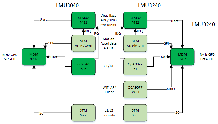
Hardware block diagram for LMU3040 and LMU3240
Acronyms
| Acronym | Description |
|---|---|
| DUT | Device Under Test |
| JPOD2 | Heavy duty Vehicle Bus Protocol interface unit, Revision 2 |
| VBUS | Vehicle Bus |
| VBU2 | Vehicle Bus Controller Revision 2 |
| VPOD2 | Light duty Vehicle Bus Protocol Interface unit, Revision 2 |
Updated about 3 years ago
